4 Bit Full Adder Truth Table - Truth Table of Full Adder-subtractor | Download Scientific ... - Finally a half adder can be made using a xor gate and an and gate.
4 Bit Full Adder Truth Table - Truth Table of Full Adder-subtractor | Download Scientific ... - Finally a half adder can be made using a xor gate and an and gate.. The final truth table is the result of the sum of the above twice with a carry in and out function and the results. The article deals about the full adder circuit with the basic gates, truth table, equations and the verilog code. So what we need to do is on paper write down every possible sum and every possible result and if a carry. Here is the advantage of full adder circuit. Solved adders draw the circuit diagram for a half adder.
The applications are also discussed. Thank you for the help! 4 bit parallel adder and 8 bit full adder how an xor gate is used here to change the adder into a subtractor by inverting the b inputs can be seen from the truth table for an xor gate, shown in table 4.1.3 (in fig. • 1,1 млн просмотров 6 лет назад. Truth table for full adder implementation will be
2 Bit Adder Truth Table - slidesharetrick from www.researchgate.net Solved adders draw the circuit diagram for a half adder. Since any addition where a carry is present isn't complete without adding the carry, the operation is not complete. The sum is the sum of bit a and b. Output variables = s, cout where s = sum and cout = carry. Adding digits in binary numbers with the full adder involves handling the carry from one digit to the next. Full subtractor using half subtractor. The outputs of a combinational logic circuit depend on the present input only. Binary adders are implemented to add two binary numbers.
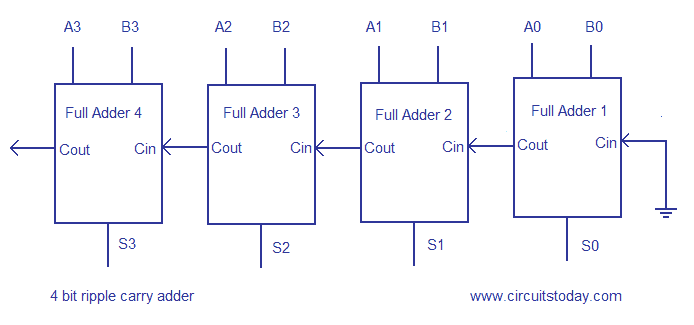
We can cascade single bit full adder circuits and could add two multiple bit binary numbers.
The carry bit output is given by the relationship. 4 bit binary full adder b1r plastic package order codes. By using equations above we can drive truth table for full adder. M54hc283f1r m74hc283m1r m74hc283b1r for the 1 bit full adder the design begins by drawing the truth table for the three input and the corresponding output sum and carry. Half adder and full adder circuit with truth tables. For sum i received a xor b xor carry in. Here is the advantage of full adder circuit. Full adder is a combinational circuit, which performs the addition of three bits a, b and cin. We can cascade single bit full adder circuits and could add two multiple bit binary numbers. The article deals about the full adder circuit with the basic gates, truth table, equations and the verilog code. Truth table for incrementing and decrementing 4 bit numbers. These full adders can also can be expanded to any number of bits space allows. The xor gate can be made using two nots, two ands and one or.
We can cascade single bit full adder circuits and could add two multiple bit binary numbers. The and gate produces a logic 1 at the carry output when both a and b are 1. Half adder and full adder circuit with truth tables. Full subtractor using half subtractor. The sum is the sum of bit a and b.
Digital Electronics | BCD Adder - GeeksforGeeks from cdncontribute.geeksforgeeks.org The half adder truth table. Sum outputs a operand inputs b operand inputs carry input carry output ground (0v) positive supply voltage. The sum is the sum of bit a and b. Full adder using truth table. For designing a half adder logic circuit, we first have to draw the truth table for two input variables i.e. Here is the advantage of full adder circuit. A 4 x n binary adder is easily built up by cascading without any additional logic. The final truth table is the result of the sum of the above twice with a carry in and out function and the results.
The truth table and corresponding karnaugh maps for it.
As an example, here's how to do an 8 bit adder. Thus the schematic for full adder using nor gate will be : Four bit full adder tutorial. 4 bit binary full adder b1r plastic package order codes. Full adder is beneficial in terms of the addition of multiple bits. By using equations above we can drive truth table for full adder. • 1,1 млн просмотров 6 лет назад. 4 bit parallel adder and 8 bit full adder how an xor gate is used here to change the adder into a subtractor by inverting the b inputs can be seen from the truth table for an xor gate, shown in table 4.1.3 (in fig. Sum outputs a operand inputs b operand inputs carry input carry output ground (0v) positive supply voltage. Binary adders are implemented to add two binary numbers. How to design a half adder circuit? From the truth table of a full adder and a karnaugh map, i obtained the functions of the sum and carry out outputs. The truth table of half adder is shown below.
The half adder truth table. The article deals about the full adder circuit with the basic gates, truth table, equations and the verilog code. The carry bit output is given by the relationship. The truth table of half adder is shown below. 4 bit parallel adder and 8 bit full adder how an xor gate is used here to change the adder into a subtractor by inverting the b inputs can be seen from the truth table for an xor gate, shown in table 4.1.3 (in fig.
Stuck at Testing of Digital Combinational Logic Part 2 from accendoreliability.com The truth table of half adder is shown below. This adder features full internal look ahead across all four bits. These full adders can also can be expanded to any number of bits space allows. Full subtractor using half subtractor. Full adder is beneficial in terms of the addition of multiple bits. The outputs of a combinational logic circuit depend on the present input only. Four bit full adder tutorial. This circuit consists, in its most basic form of two gates, an xor gate that produces a logic 1 output whenever a is 1 and b is 0, or when b is 1 and a is 0.
The sum is the sum of bit a and b.
The sum is the sum of bit a and b. It is used for the purpose of adding two single bit numbers with a carry. As full adder circuit deal with three inputs, the truth table also updated with three input columns and two output columns. 4 bit parallel adder and 8 bit full adder how an xor gate is used here to change the adder into a subtractor by inverting the b inputs can be seen from the truth table for an xor gate, shown in table 4.1.3 (in fig. Binary adders are implemented to add two binary numbers. The and gate produces a logic 1 at the carry output when both a and b are 1. M54hc283f1r m74hc283m1r m74hc283b1r for the 1 bit full adder the design begins by drawing the truth table for the three input and the corresponding output sum and carry. Four bit full adder tutorial. The carry bit output is given by the relationship. Truth table for a full subtractor. The final truth table is the result of the sum of the above twice with a carry in and out function and the results. How to design a half adder circuit? Thus, full adder has the ability to perform the addition of three bits.
You have just read the article entitled 4 Bit Full Adder Truth Table - Truth Table of Full Adder-subtractor | Download Scientific ... - Finally a half adder can be made using a xor gate and an and gate.. You can also bookmark this page with the URL : https://dinujexx.blogspot.com/2021/05/4-bit-full-adder-truth-table-truth.html
Share Awesome
Belum ada Komentar untuk "4 Bit Full Adder Truth Table - Truth Table of Full Adder-subtractor | Download Scientific ... - Finally a half adder can be made using a xor gate and an and gate."


Belum ada Komentar untuk "4 Bit Full Adder Truth Table - Truth Table of Full Adder-subtractor | Download Scientific ... - Finally a half adder can be made using a xor gate and an and gate."
Posting Komentar